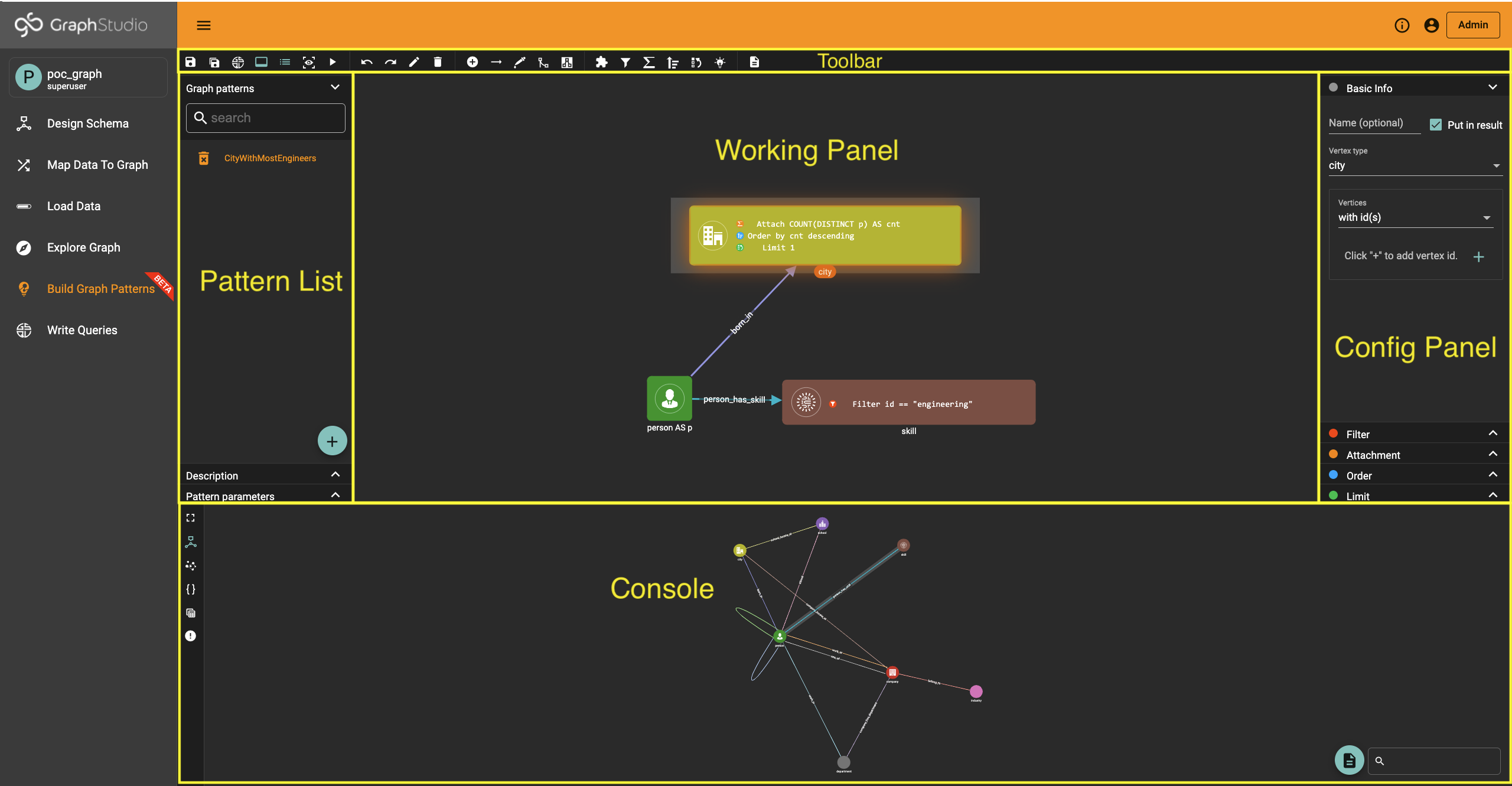
Visual Query Builder
Visual Query Builder(VQB) provides a visual approach to building your graph business logic. In the Build Graph Patterns page, you can create visual patterns in a drag-and-drop fashion to represent the questions you want to ask instead of writing GSQL queries.
By adding the Visual Query Builder component, GraphStudio becomes a complete visual SDK for users to build graph applications from end to end without writing a single line of code!
Currently, Visual Query Builder is still in beta phase. Please expect lots of improvements and changes coming in the future!
Basic Concepts
A visual pattern is a declarative way of describing a template subgraph structure, and all the subgraph structures that the visual pattern is homomorphic with are valid matching results.
Visual patterns are constructed by vertex patterns, edge patterns, widgets and pattern views.
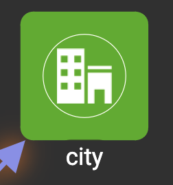
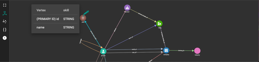
This is a basic vertex pattern within a visual pattern:
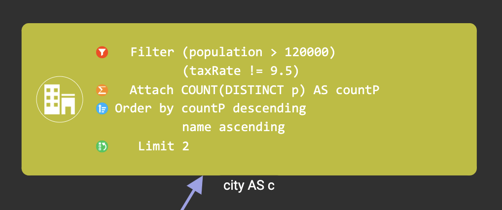
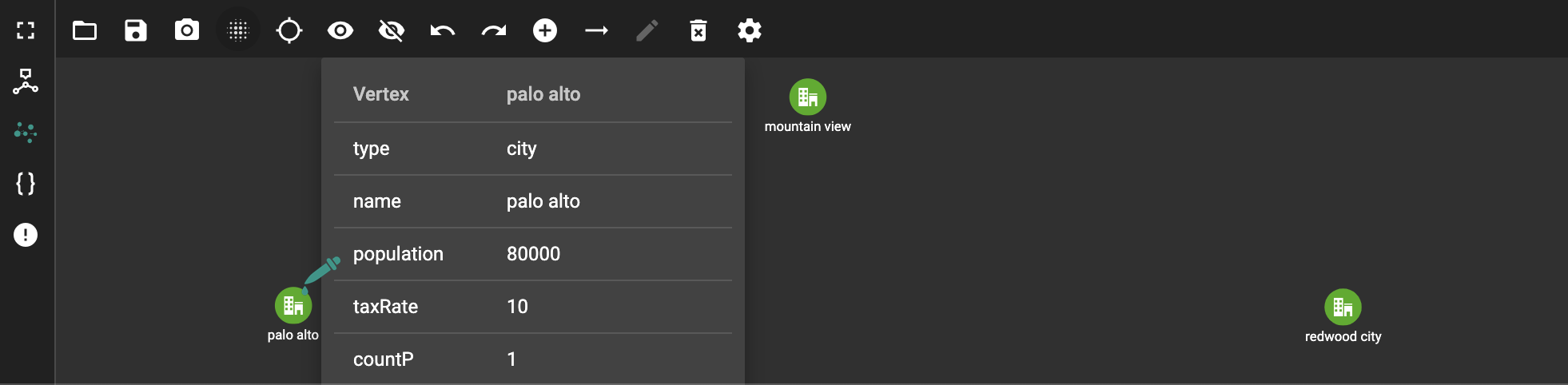
This is a vertex pattern with 2 filters, 1 attachment, 2 ordering, and limit:
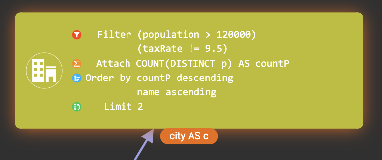
This is a vertex pattern that will be output in the pattern execution result. You can see the glow around the border and the highlight at the label:
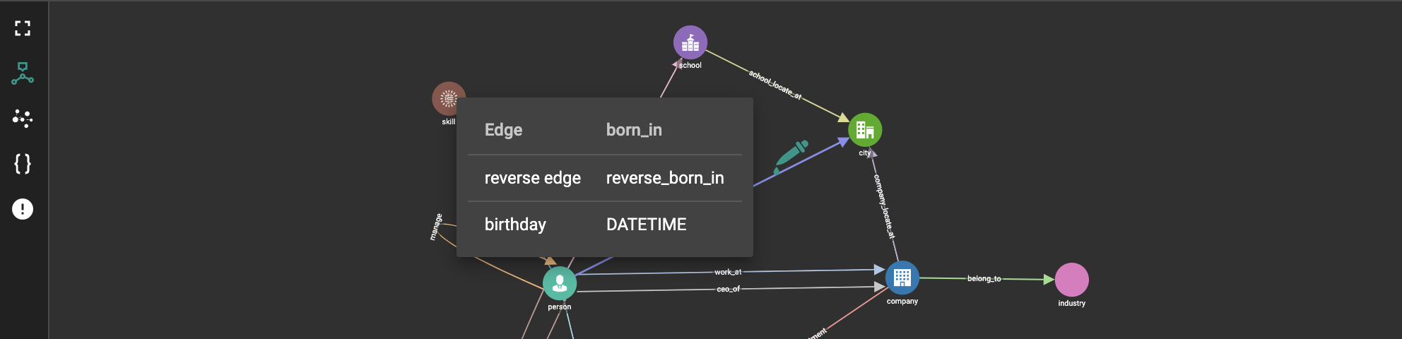
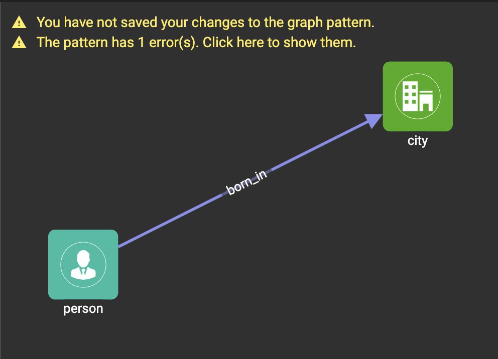
This is a basic edge pattern:
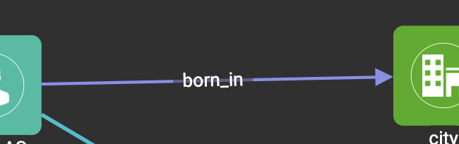
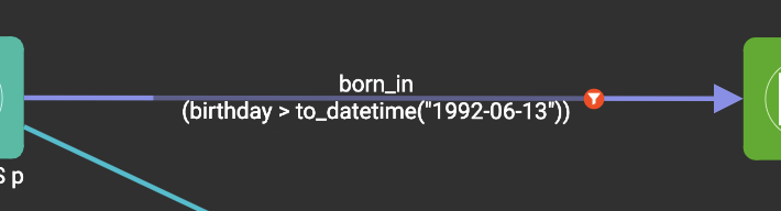
This is an edge pattern with 1 filter:
This is an edge pattern that will be output in the pattern execution result:
This is a union widget:
A widget has input vertex patterns and output vertex patterns:
This is a visual pattern with a pattern view:app-name:
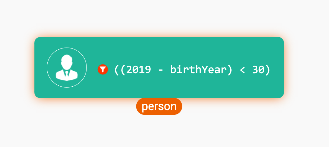
This is the visual pattern matching all the people who are younger than 30 years old in the year 2019. The filter ((2019 - birthYear) < 30) on the person vertex pattern provides the matching condition:
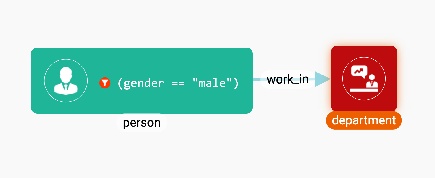
This is the visual pattern matching all the departments having at least one male employee:
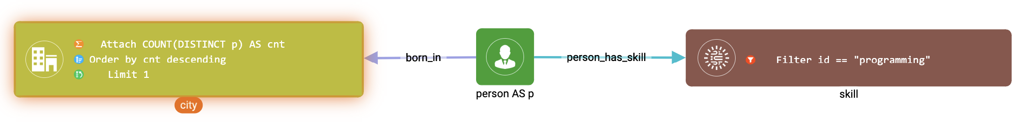
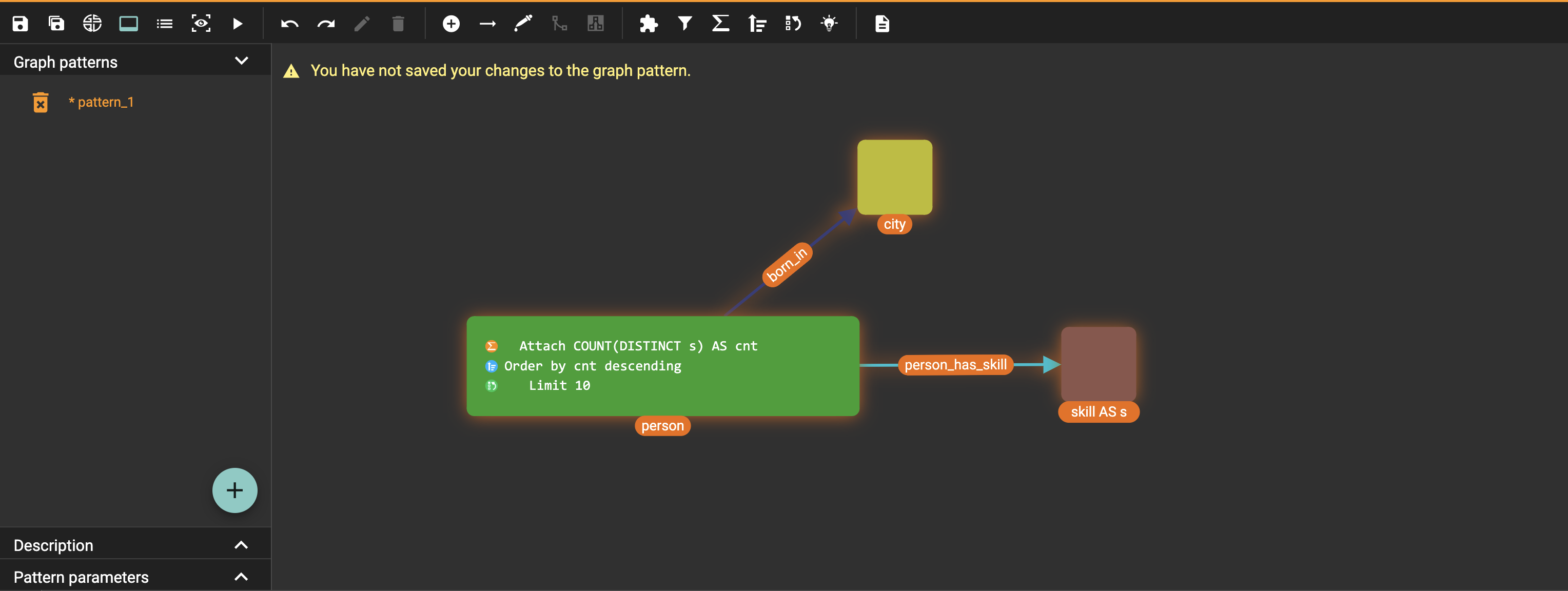
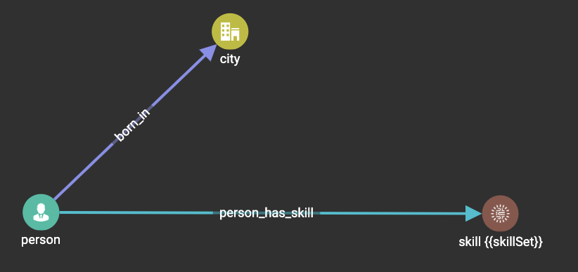
This is the visual pattern that matches the hometown of the most people having the programming skill. The attachment COUNT(DISTINCT p) as cnt annotates the number of people born in each city that have the programming skill. Then we order the city vertices by their descending cnt value, and choose the top 1 city:
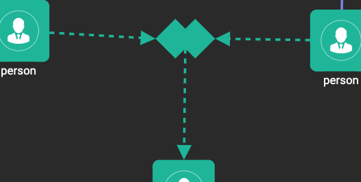
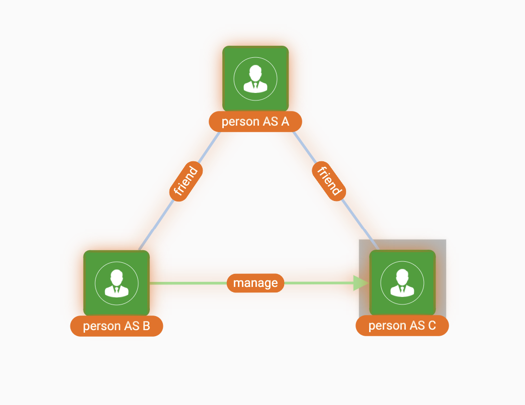
This is the visual pattern matching all such three persons A, B and C, where A is B’s friend, and A is C’s friend, and B is C’s manager:
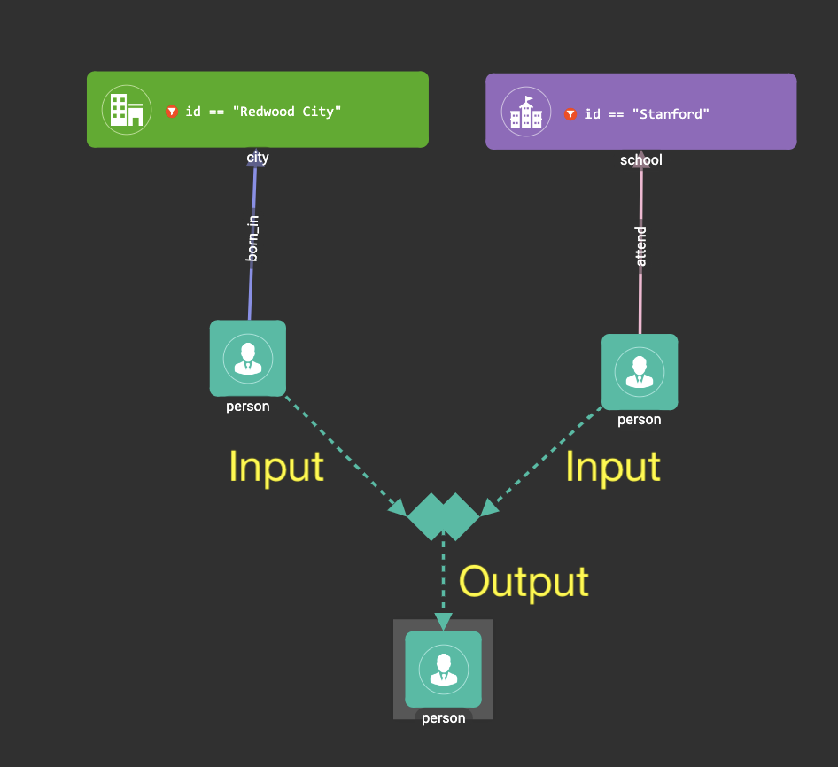
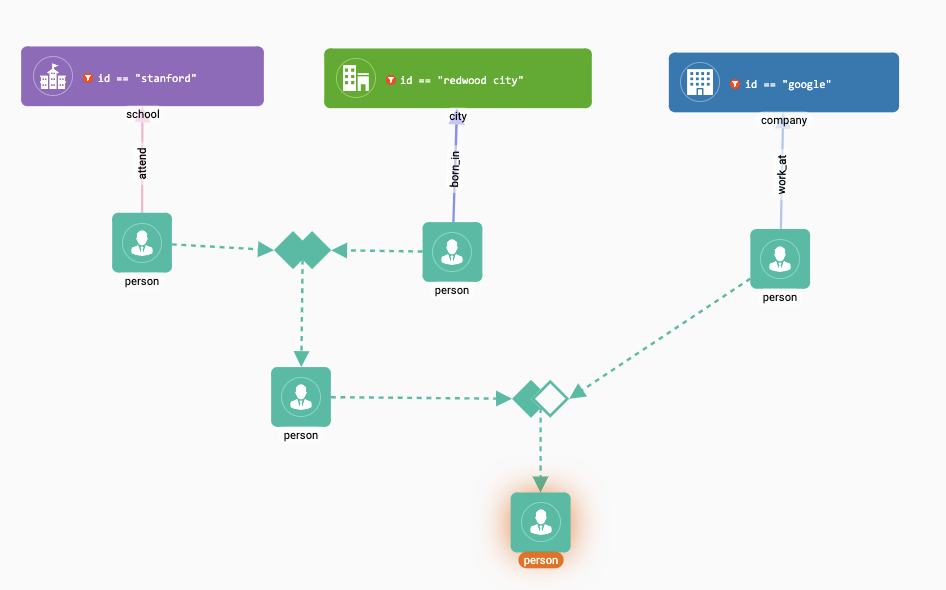
This visual pattern matches all the people that born in Redwood City and attended Stanford university, but didn’t work for Google:
Now you have a first sight about how the visual patterns look like. Let’s walk through all the concepts in depth.
Working Panel
Working panel is the central component (both visually and logically) of Visual Query Builder. Your visual patterns are rendered here.
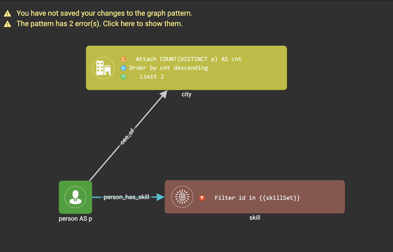
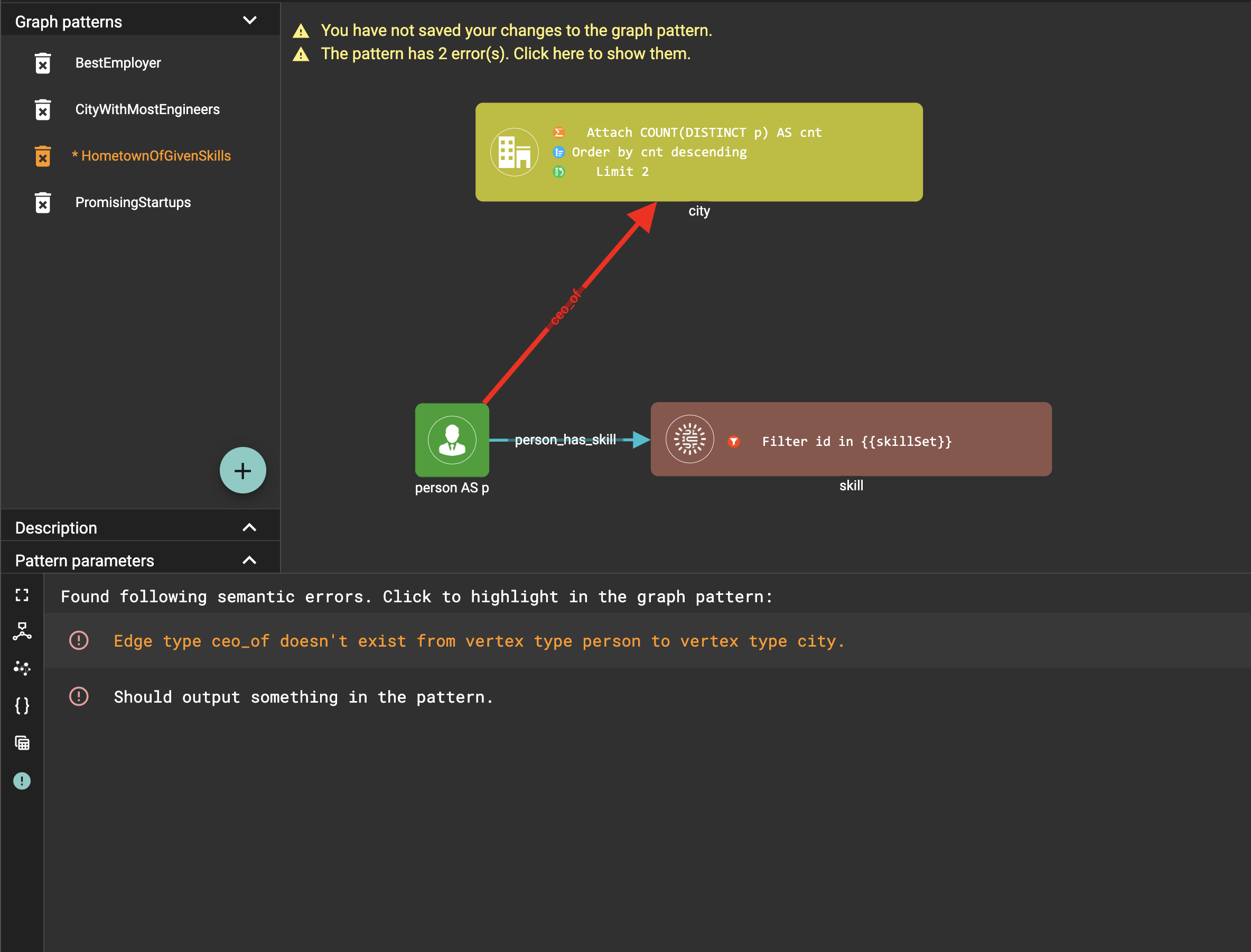
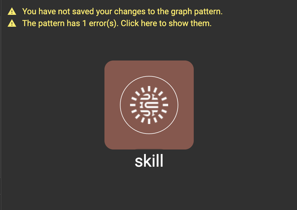
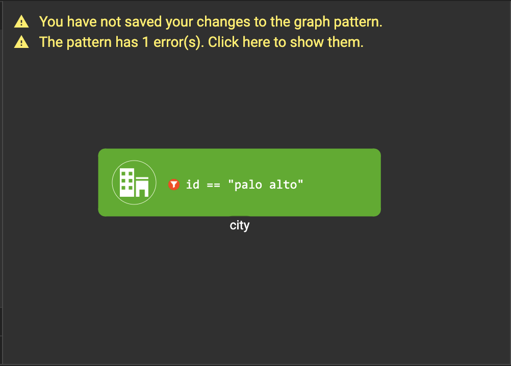
Like other pages in GraphStudio, you can zoom-in, zoom-out and drag the visual pattern. If you have unsaved changes to the pattern, or containing errors in the pattern, some warning messages will show in the top left corner of working panel:
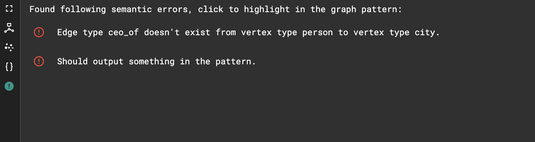
If you click the message indicating errors, the Console will switch to Problems tab:
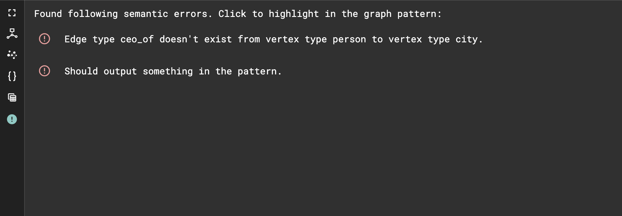
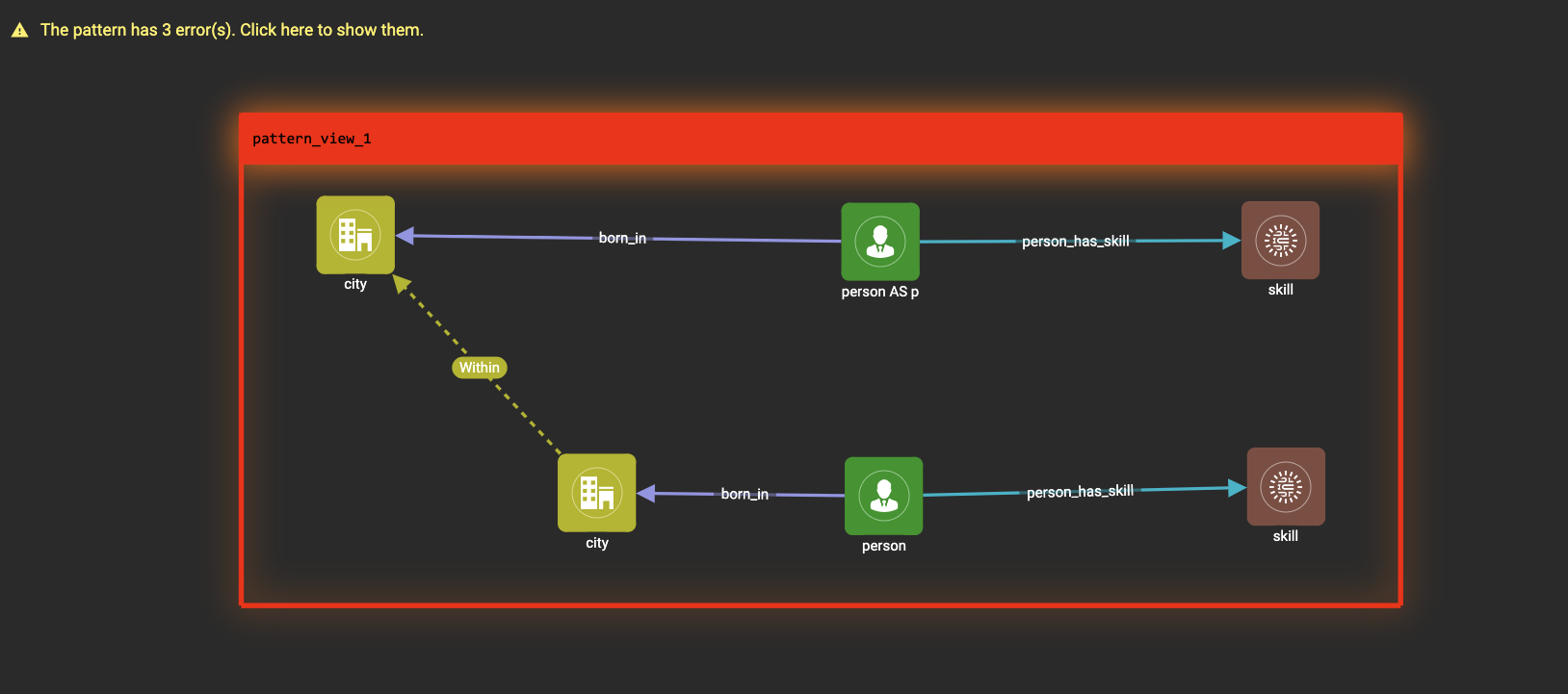
You can click the error messages. For some errors, the vertex patterns, edge patterns and widgets involved in the error will be marked red to facilitate your debugging:
Pattern List
The pattern list panel contains three sections:
Graph patterns
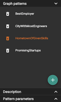
The graph patterns section lists all the visual patterns you have
created for current graph. You can
click  to create
new patterns, or
click
to create
new patterns, or
click  to delete
existing ones.
to delete
existing ones.
Description
Other than the visual view of the graph pattern, you can optionally add a description for the pattern. This can help other users to understand what problem you are trying to solve.

After changing the description, don’t forget to confirm the change:

Changing description is considered as a change to the visual pattern, don’t forget to save the pattern in the end.

Toolbar
The toolbar options, from left to right, are the following:
| Toolbar option | Functionality |
|---|---|
|
Save the graph pattern. |
|
Save the graph pattern as a different pattern under a new name. |
|
Save as GSQL query: show the GSQL query generated from the pattern and save. See more information at Save as GSQL Query. |
|
Console: open/close the console panel. |
|
Configuration panel: open/close the config panel. By default, the config panel is closed. You can either open the panel by clicking this button, or double-click a vertex pattern or edge pattern in the visual pattern to open the config panel. |
|
Render pattern options: config how much detail is shown on the pattern. See more information here. |
|
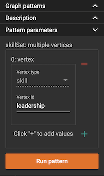
Run: run the visual pattern. If the pattern doesn’t have any parameters, it will run directly, otherwise the Pattern parameters section will expand for you to provide the parameter values. |
|
Undo and redo: undo and redo the changes on the visual pattern. The whole editing history of each visual pattern since entering Build Graph Patterns page is preserved. |
|
Edit: edit the selected vertex pattern or edge pattern. This is same as double-clicking one vertex or edge pattern. |
|
Delete: delete selected vertex patterns, edge patterns and widgets. You can hold the Shift key to select multiple elements to delete. |
|
Add a vertex pattern: add a new vertex pattern into the current visual pattern. |
|
Add an edge pattern: add a new edge pattern into the current visual pattern. |
|
Pick: a shortcut for adding vertex patterns and edge patterns into the visual pattern. |
|
Merge: select multiple vertex patterns, and click this button to merge them together. This is a fast way to connect multiple shorter patterns into a longer one. |
|
Add a pattern view: select one or more vertex or edge patterns, and click this button to create a pattern view containing all these vertex and edge patterns. |
|
Widget: see more information here. |
|
Filter: click this button then click a vertex pattern or edge pattern, and the config panel will enter editing mode for the selected vertex or edge pattern, with the Filter section expanded. |
|
Attachment: click this button then click a vertex pattern, and the config panel will enter editing mode for the selected vertex pattern, with the Attachment section expanded. |
|
Order by: click this button then click a vertex pattern, and the config panel will enter editing mode for the selected vertex pattern, with the Order section expanded. |
|
Limit: click this button then click a vertex pattern, and the config panel will enter editing mode for the selected vertex pattern, with the Limit section expanded. |
|
Output: click this button, then click vertex patterns and edge patterns of the visual pattern to toggle whether to output them or not. You can see the output glow of the selected vertices or edges turning on and off. |

.png)


Configuration Panel
You can edit vertex patterns and edge patterns from the Configuration Panel.
If you want to use vertex ID or edge ID as an attribute, check the "AS ATTRIBUTE" box in the Design Schema section for the corresponding vertex type. If a vertex or edge type’s primary ID is set as an attibute, you can use its ID in features such as filter, attachment and order by like any other attribute.
Vertex patterns
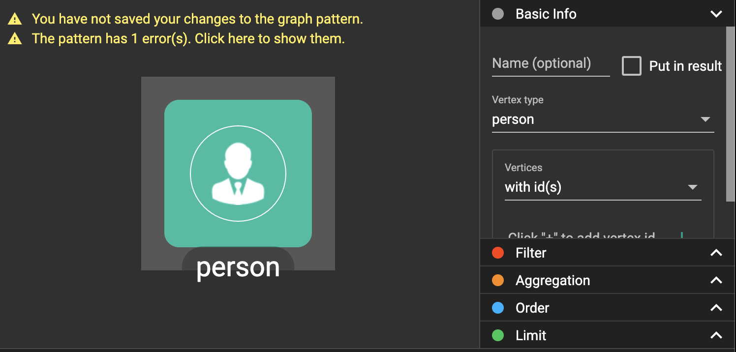
If you enter editing mode of a vertex pattern and expand the Basic Info section, you can edit its name, decide whether or not to put it into result, change its vertex type, provide optional matching conditions by giving a list of ids, or provide a parameter name.

The name supplied in the panel will be used as the vertex’s JSON key when producing output and when the pattern is saved as a GSQL query.
You can add/drop IDs in the list:

Or add an input parameter:

Basic Info for edge pattern
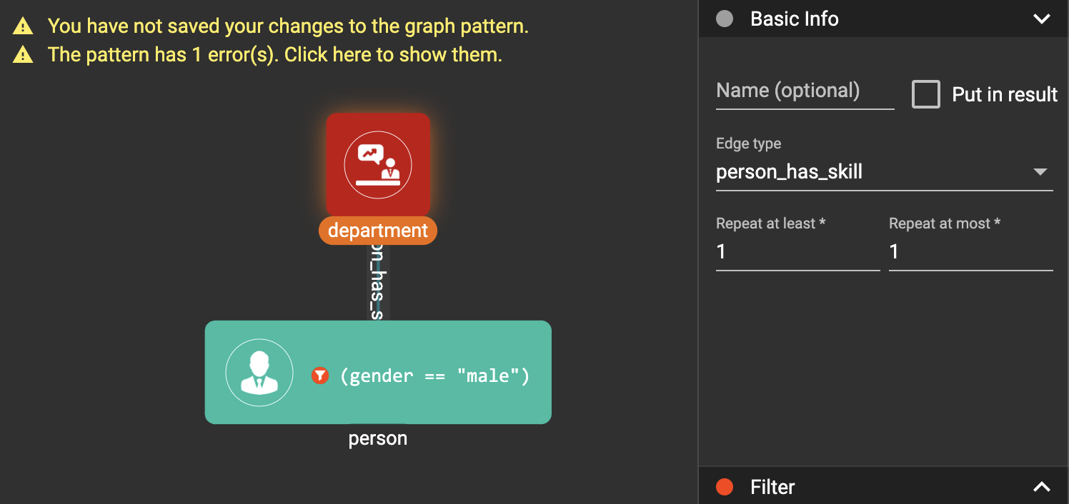
If you enter editing mode of an edge pattern and expand the Basic Info section, you can edit its name, decide whether or not to put it into result, or change its edge type. You can also specify this edge pattern as a regex match by providing Repeat as least (a non-negative integer) and Repeat at most (a positive integer). Due to current GSQL limitations, if you decide to change these numbers, you cannot give the edge pattern a name or put it into result.

The name supplied in the panel will be used as the edge’s JSON key when producing output and when the pattern is saved as a GSQL query.
When finished editing, you need to confirm the change. You can also cancel the change if you made a mistake:

| If you want another vertex pattern or edge pattern to refer to current selected vertex or edge pattern’s attributes, you need to give it a name. |
Filter
If you expand the Filter section, you can add/edit/delete filters for the selected vertex or edge pattern:
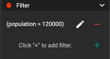
Click  besides the filter
expression and enter editing mode of the filter:
besides the filter
expression and enter editing mode of the filter:
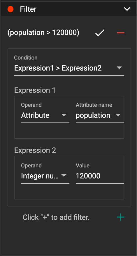
You can add multiple filters for each vertex and edge pattern, and they are AND relationship when executing the pattern. Building the filter is similar with building attribute filter in Explore Graph page.
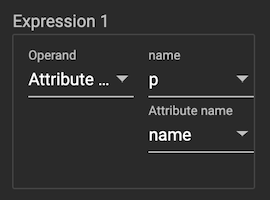
One thing special here is that you can refer to attributes on other vertex patterns and edge patterns. Choose Attribute of vertex or edge as expression type, then choose the name of the vertex or edge pattern whose attribute you want to refer to (see above why we need give a name to vertex or edge patterns), then choose the attribute you want to refer to.
When finished with editing, you need confirm or cancel the change:

Attachment
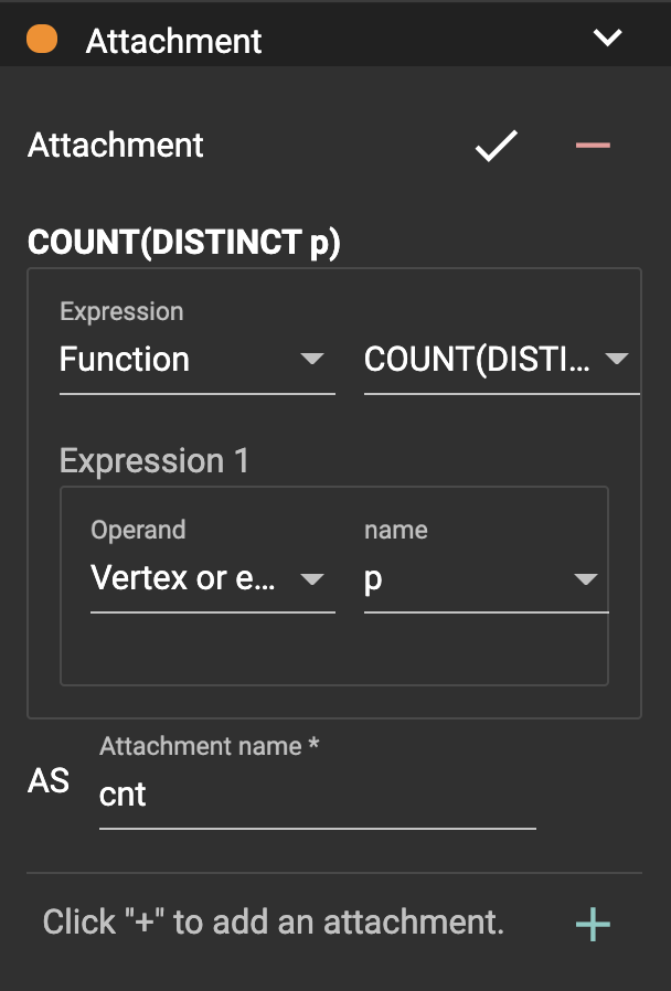
If you expand the Attachment section, you can add/edit/delete attachments for the selected vertex pattern (attachment on edge patterns is not supported):
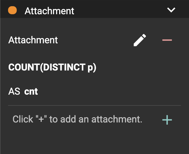
Click beside one
attachment and enter editing mode for the attachment. You can edit
both the attachment expression and attachment name:
When finished with editing, you need to confirm or cancel the change:

In attachments, you can either attach a single value or attach the results of an aggregation function, to all the matched vertex entity results.
Attaching a single value means attaching the given value to all vertex entities within the matched result. If for example, you choose to attach the integer value 1, then that value will be attached to all the matched vertex entity results where the attachment was applied to. If the attachment is applied to an entity that is involved in multiple matches, then the attached value is non-deterministic.
Attaching the results of an aggregation function means grouping all the matching results by the vertex entity which match the vertex pattern, and then aggregated based on the expression.
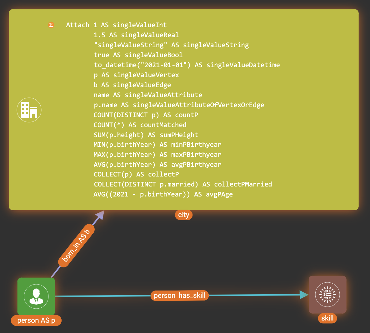
Take this example:
| name | attachment expression | explanation |
|---|---|---|
singleValueInt |
1 |
Attach the integer number |
singleValueReal |
1.5 |
Attach the real number |
singleValueString |
"singleValueString" |
Attach the string "singleValueString" to each matched city vertex. |
singleValueBool |
true |
Attach the boolean value |
singleValueDatetime |
2021-01-01 |
Attach the datetime value |
singleValueVertex |
p |
Attach one of the vertex ids of the matched vertices p to the matched city vertex connected to vertices p. |
singleValueEdge |
b |
Attach one of the edge ids of the matched edges b_i to the matched city vertex with edges b. |
singleValueAttribute |
name |
Attach the attribute name of the matched city vertex to the matched city vertex itself. |
singleValueAttributeOfVertexOrEdge |
p.name |
Attach one of the |
countP |
COUNT(DISTINCT p) |
Count number of distinct person vertices matched to each city vertex. |
countMatched |
COUNT(*) |
Count number of matches each city vertex involves in. |
sumPHeight |
SUM(p.height) |
Sum the height attribute of all person vertices matched to each city vertex. |
minPBirthyear |
MIN(p.birthYear) |
Get the minimal height attribute of all person vertices matched to each city vertex. |
maxPBirthyear |
MAX(p.birthYear) |
Get the maximal height attribute of all person vertices matched to each city vertex. |
avgPBirthyear |
AVG(p.birthYear) |
Get the average value of height attribute of all person vertices matched to each city vertex. |
collectP |
COLLECT(p) |
Collect all person vertices matched to each city vertex. |
collectPMarried |
COLLECT(DISTINCT p.married) |
Collect all distinct person vertices' married status matched to each city vertex. |
avgPAge |
AVG2021 - p.birthYear |
Calculate the average age of all person vertices matched to each city vertex. |
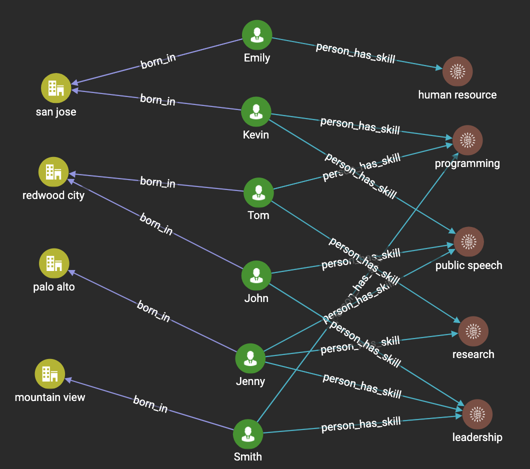
Consider we have the following matching result:

We have the following attachment result table for city vertex san jose:
| City vertex | Attachment result | Explanation |
|---|---|---|
san jose |
singleValueInt = 1 |
Just attach the integer number |
san jose |
singleValueReal = 1.5 |
Just attach the real number |
san jose |
singleValueString = singleValueString |
Just attach the string value "singleValueString" on the matched city vertex. |
san jose |
singleValueBool = true |
Just attach the boolean value |
san jose |
singleValueDatetime = ["2020-01-01 00:00:00"] |
Just attach the datetime value |
san jose |
singleValueVertex = ["Emily"] OR singleValueVertex = ["Kevin"] |
There are two person vertices connected to city vertex san jose "Emily" and "Kevin". The resulting value stored in singleValueVertex is non deterministic and could be either "Emily" or "Kevin". |
san jose |
singleValueEdge = [ { "attributes": { "birthday": "1992-05-23 00:00:00" }, "directed": true, "e_type": "born_in", "from_id": "Emily", "from_type": "person", "to_id": "san jose", "to_type": "city" } ] OR singleValueEdge = [ { "attributes": { "birthday": "1992-05-23 00:00:00" }, "directed": true, "e_type": "born_in", "from_id": "Emily", "from_type": "person", "to_id": "san jose", "to_type": "city" } ] |
The city vertex san jose is connected to two born in edges, one of them connects the san jose vertex to the person vertex "Kevin" and the second edge connects the san jose vertex to the person vertex "Emily". The resulting value stored in singleValueEdge is non deterministic and could be either one of these edges. |
san jose |
singleValueAttribute = redwood city |
The city vertex san jose has the attribute |
san jose |
singleValueAttributeOfVertexOrEdge = Emily OR singleValueAttributeOfVertexOrEdge = Kevin |
The city vertex san jose is connected to two person vertices,
one of them has the attribute |
san jose |
countP = 2 |
Kevin and Emily |
san jose |
countMatched = 3 |
(san jose)←[born_in]-(Kevin)-[person_has_skill]→(programming) (san jose)←[born_in]-(Kevin)-[person_has_skill]→(public speech) (san jose)←[born_in]-(Emily)-[person_has_skill]→(human resource) |
san jose |
sumPHeight = 511 |
Kevin.height + Kevin.height + Emily.height = 173 + 173 + 165 |
san jose |
minPBirthyear = 1991 |
Min(Kevin.birthYear, Kevin.birthYear, Emily.birthYear) |
san jose |
maxPBirthyear = 1992 |
Max(Kevin.birthYear, Kevin.birthYear, Emily.birthYear) |
san jose |
avgPBirthyear = 1991.33333 |
(Kevin.birthYear + Kevin.birthYear |
san jose |
collectP = [Kevin, Kevin, Emily] |
|
san jose |
collectPName = [false] |
Both Kevin and Emily’s married status is false. |
san jose |
avgPAge = 29.6667 |
2021 - Kevin.birthYear) + (2021 - Kevin.birthYear) + (2021 - Emily.birthYear / 3 |
As you can see above the values of attaching a single value for datetime, vertex and edge are stored in a list. This is because,
we currently do not have an accumulator to store these data types directly yet.
The data types supported for single value attachments are: integer, real, string, bool, datetime, vertex and edge.
Order
If you expand the Order section, you can add/edit/delete ordering for the selected vertex pattern (ordering on edge patterns is not supported):
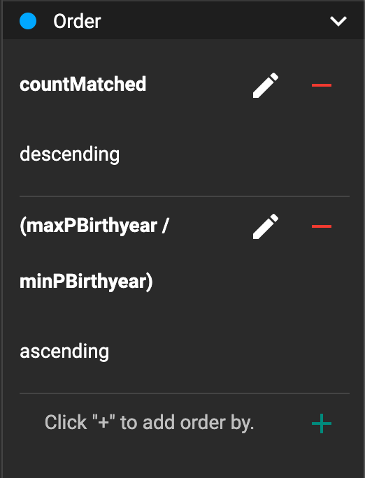
Click beside the ordering
and enter editing mode for the ordering. You can edit both the ordering
expression and whether results are in ascending or descending order:
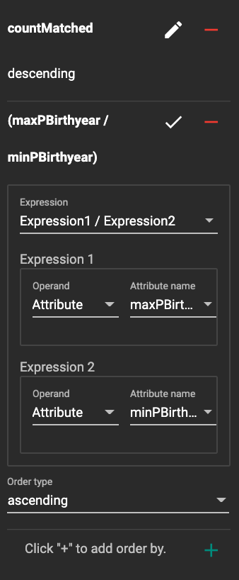
When finished with editing, you need to confirm the change.
You can refer to attachments in ordering expression. You can add
multiple orderings, which follow the multi-key ordering rule (upper
ordering dominates). We support ordering by data of types: integer,
real, string and datetime. However, single value attachments with
the type datetime are stored in a list, thus, we currently do not
support ordering based on single value attachments that have the datetime
data type.
Limit
If you only want a subset of your matching result, you can use limit. Only the top limit results will be returned based on your ordering settings. If you don’t have orderings, the result will be randomly picked from all matchings.
If you expand the Limit section, you can add/edit/delete limit for the selected vertex pattern (limit on edge patterns is not supported):
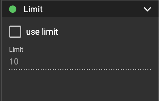
Toggle use limit checkbox to enable/disable limit. You can also edit the limit number:
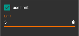
When finished editing, you need confirm or cancel the change:

Console
The Console panel shows the graph schema, the result of the last pattern execution result, and errors the visual pattern has. Each execution of a pattern generates two types of results: a visualized graph and JSON text. On the left is a toolbar with buttons for switching between the tabs. The buttons, from top to bottom, are the following:
| menu option | functionality |
|---|---|
|
Expand/Collapse: expand or collapse the Console panel. |
|
Graph schema: show the graph schema. |
|
Visualize graph result: show the visual result of the last run pattern. |
|
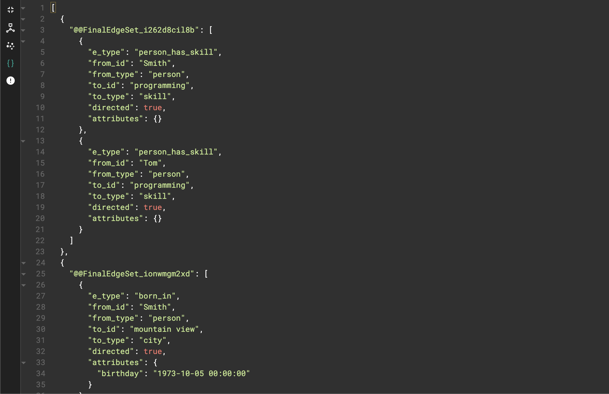
View JSON result: show the raw text result in JSON format of the last run pattern. |
|
Problems: show the errors in the visual pattern. |

.png)
.png)


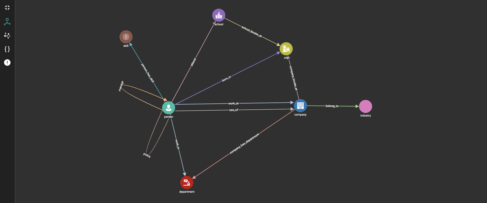
Graph schema
Viewing graph schema makes it more convenient for developers to refer to the schema topology logic and easier to construct the visual pattern.
Visualize graph result
If the pattern execution result contains a graph structure, the result will be visualized in this panel as a graph. The panel is the same as the Explore Graph panel. The only difference is that each time you run a pattern, the previous result will be erased. In Explore Graph, the results are added incrementally.
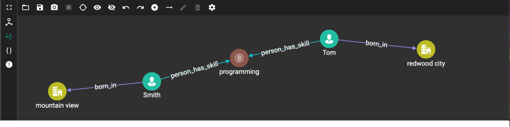
You can switch to the JSON Result panel to see the result in JSON format.
Save as
The 'Save as' feature allows users to save the current pattern as a new pattern under a new name. After clicking the 'Save as' button the user will be asked to input a unique name for the new pattern. Then, the user will be redirected to the new pattern, and the pattern the user saved as the new pattern will return to its last saved state.
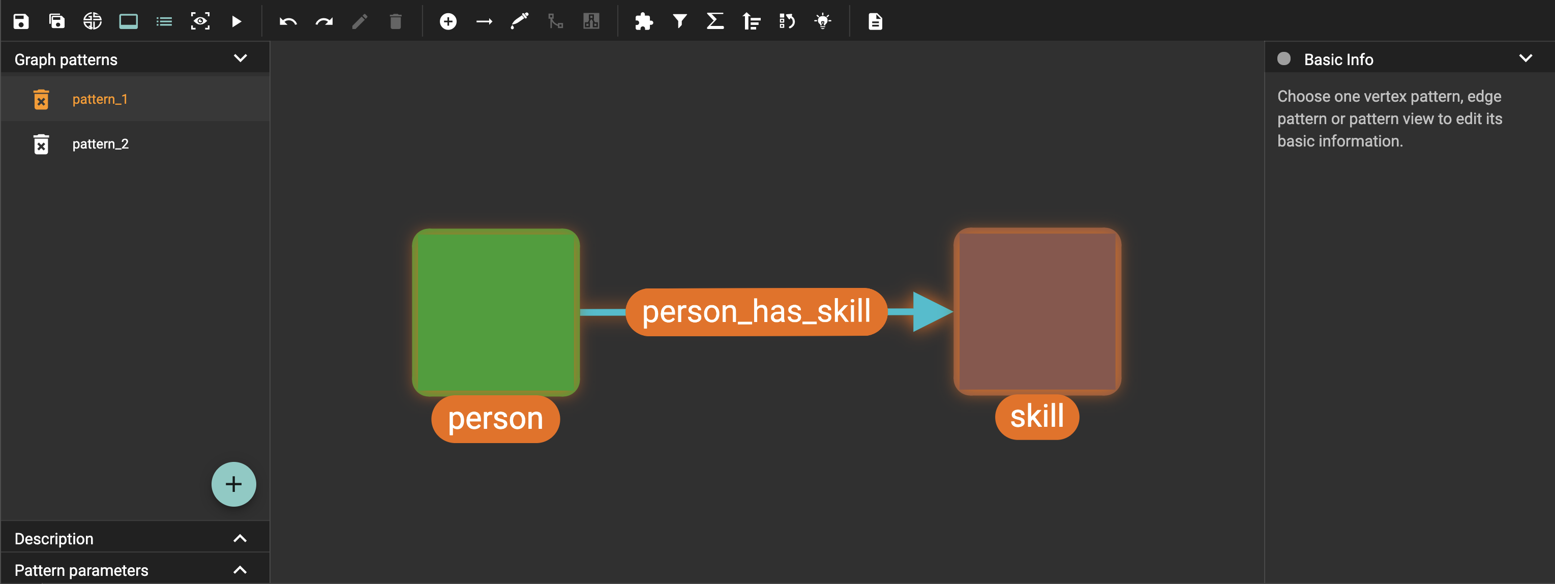
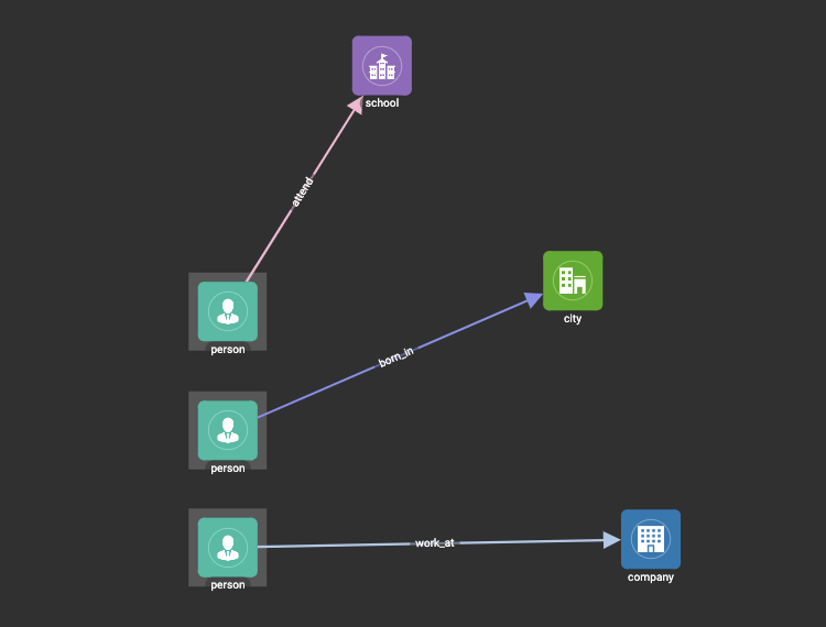
For example let us say that the user saves the following pattern:
The user then continues to make changes and then decides to save this pattern as a new pattern with a new name, and clicks on the 'Save as' button.
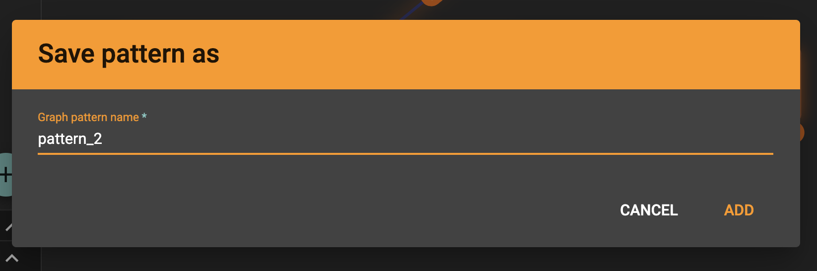
Here is the dialog that prompts the user to enter a name for the new pattern:
After entering the name the user gets redirected to the new pattern:
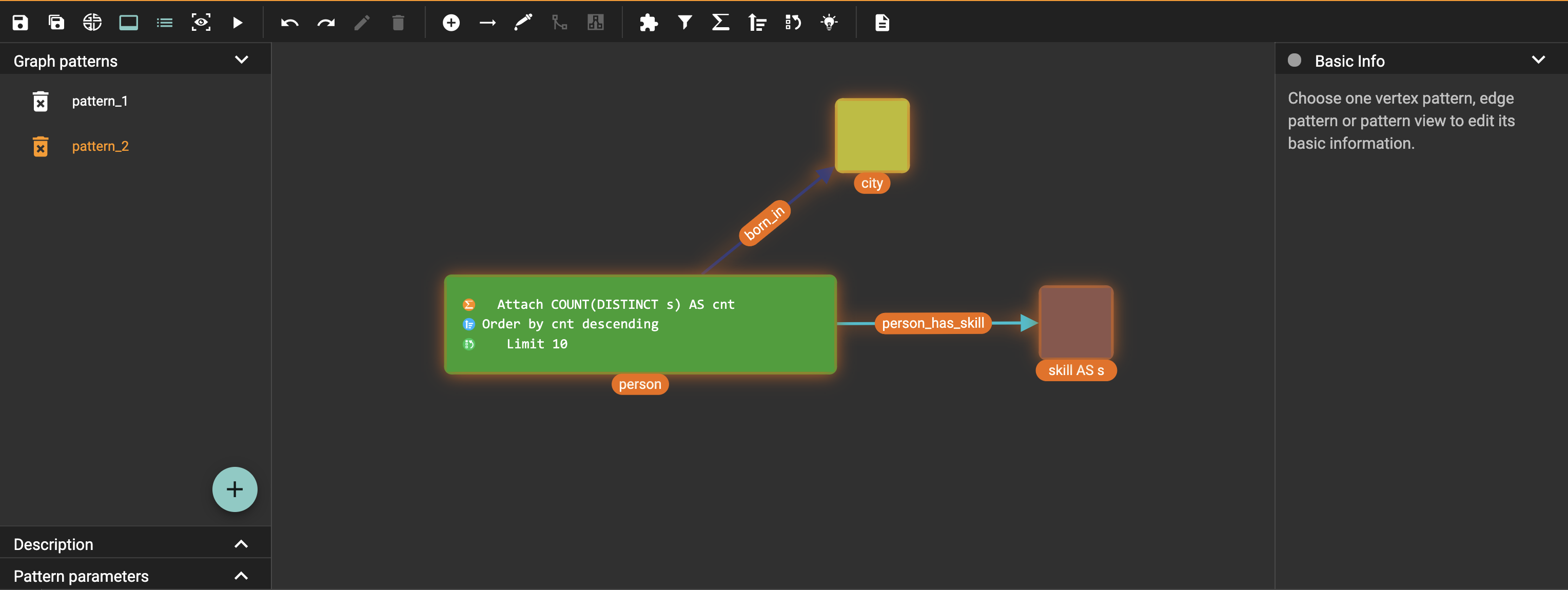
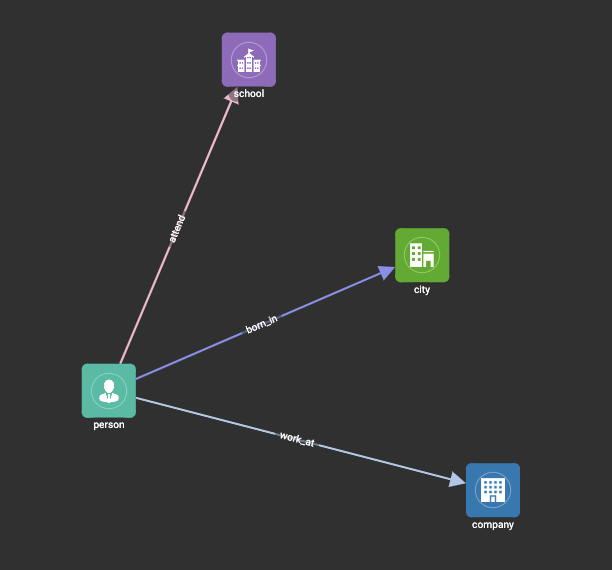
Here is the previous pattern returned to its last saved state:
The new pattern contains all the history (can undo and redo) of the previous pattern, whilst the previous pattern loses its history. This imitates the behaviour of most text editors.
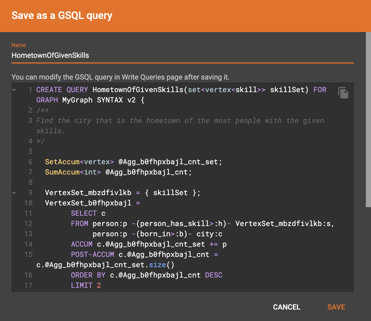
Save as GSQL query
You can view the GSQL query generated from your visual pattern and save it. Then you can access this query from Write Queries page, modify your query, interpret it, install it and run it.
Render pattern options
There are three different rendering options.
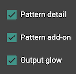
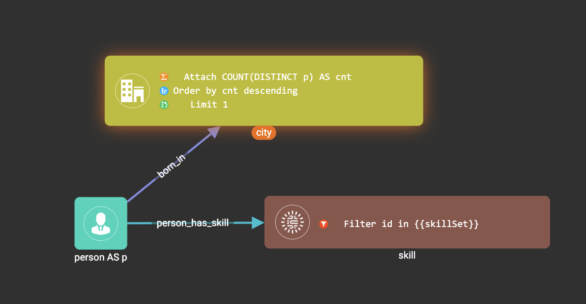
By default, Pattern detail and Output glow are checked. All the filters, attachments, ordering conditions and limits are rendered, and the vertex and edge patterns that will be in result will be highlighted with glow:
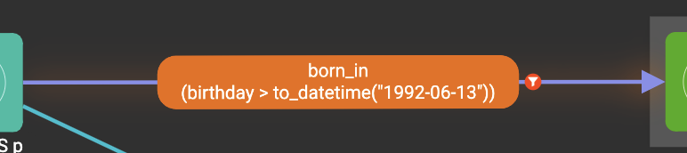
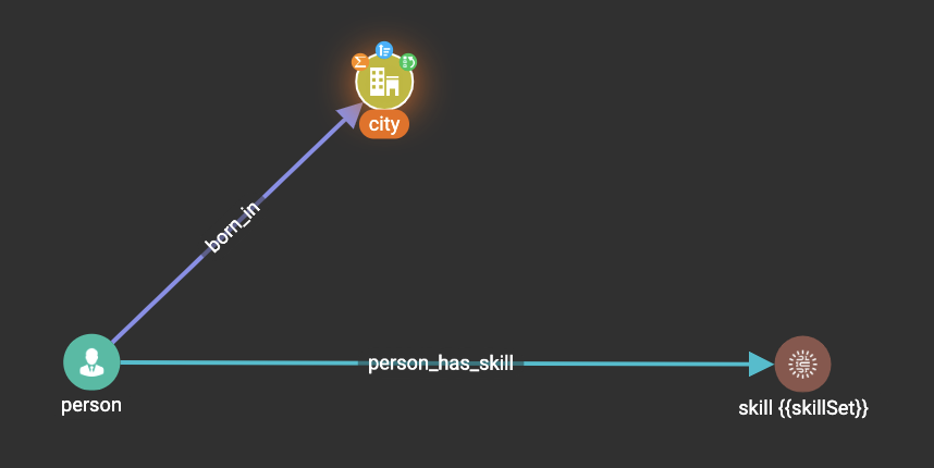
If Pattern detail is not checked, add-on marks will indicate that there are filters, attachments, ordering conditions and limits on corresponding vertex patterns and edge patterns:
If Pattern add-on is not checked, the add-ons will be hidden:
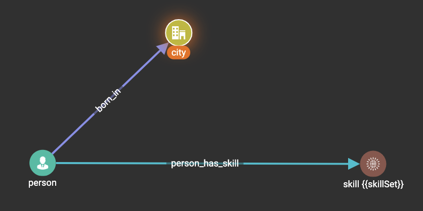
If Output glow is not checked, the output indicating glow is hidden:
Add a vertex pattern
Click  , and a
new vertex pattern will be added to the visual pattern. You are in the
editing mode of the newly added vertex pattern.
, and a
new vertex pattern will be added to the visual pattern. You are in the
editing mode of the newly added vertex pattern.
Add an edge pattern
Click  , then click
the source vertex pattern of the edge pattern:
, then click
the source vertex pattern of the edge pattern:
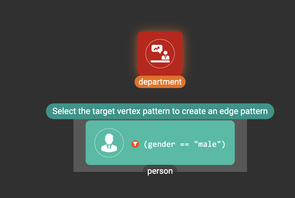
Then click the target vertex pattern of the edge pattern. A new edge pattern will be added to the visual pattern. You are in the editing mode of the newly added edge pattern:
Pick
Pick is a fast way to build your visual pattern. You can pick from either graph schema or visual result.
Click  , then click one
vertex type in the graph schema tab:
, then click one
vertex type in the graph schema tab:
A vertex pattern will be added to the visual pattern:
Click , then click one
edge type in the graph schema tab:
An edge pattern together with two vertex patterns will be added to the visual pattern:
Click , then click one
vertex in the visualize graph result tab:
A vertex pattern will be added to the visual pattern. Note that the vertex pattern contains an id condition because it is picked from an actual vertex entity from the graph:
Merge
You can merge multiple vertex patterns of the same vertex type into one vertex pattern.
Hold Shift key to select multiple vertex patterns:
Then click  , and you
will get a larger visual pattern:
, and you
will get a larger visual pattern:
Use pick and merge together and you can create a complicated visual pattern quickly.
Add a pattern view
The pattern view functionality allows us to group a subset of a visual pattern within a connected component together as a pattern view. The pattern view is applied on the pattern match results and outputs a deduplicated subset of the original match results.
To add a pattern view to your visual pattern:
-
Select the vertices and edges in the visual pattern that you want to include in the pattern view.
-
Click on the 'Add a pattern view' button
 on the toolbar to add all selected vertices and edges to the pattern view.
-
If you select an edge pattern, both vertices on the ends of the edge pattern will be included within the pattern view.
-
If you select two vertex patterns with an edge/edges between the two vertex patterns the edge/edges between the two vertex patterns will be included in the pattern view.
-
| Self edges might not visually appear to be included within the pattern view, but if the self edge or the vertex with the self edge was selected, then it is in the pattern view. |
A pattern view can only consist of vertices and edges, and so widgets are not included within a pattern view.
Each pattern view must have an alias. GraphStudio generates a default name for each pattern view upon creation, and you can change its name from the configuration panel.
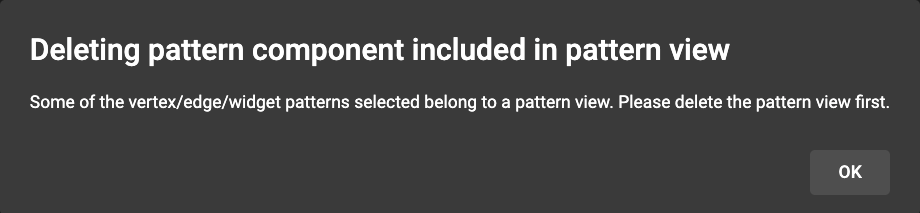
To delete a pattern view, you will need to select the pattern view and then click on the 'Delete' button on the toolbar. Vertex and edge patterns within a pattern view can not be deleted before the pattern view itself has been deleted. If you attempt to do so an error message such as the one below will be shown:
Examples
Example 1
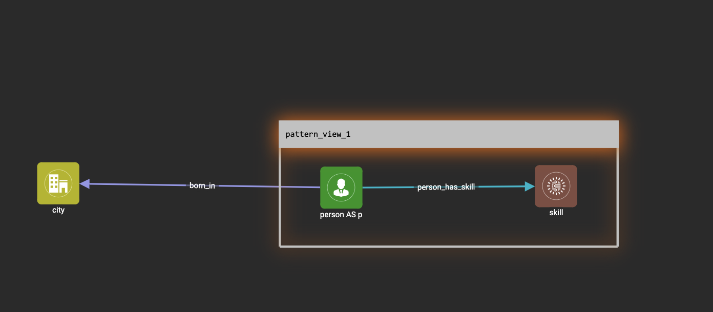
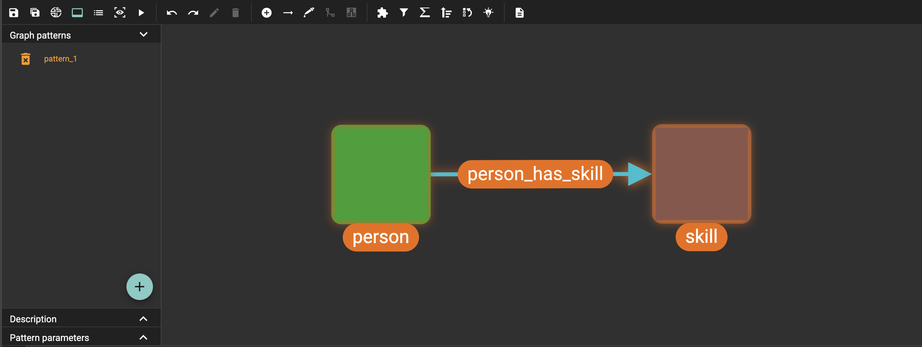
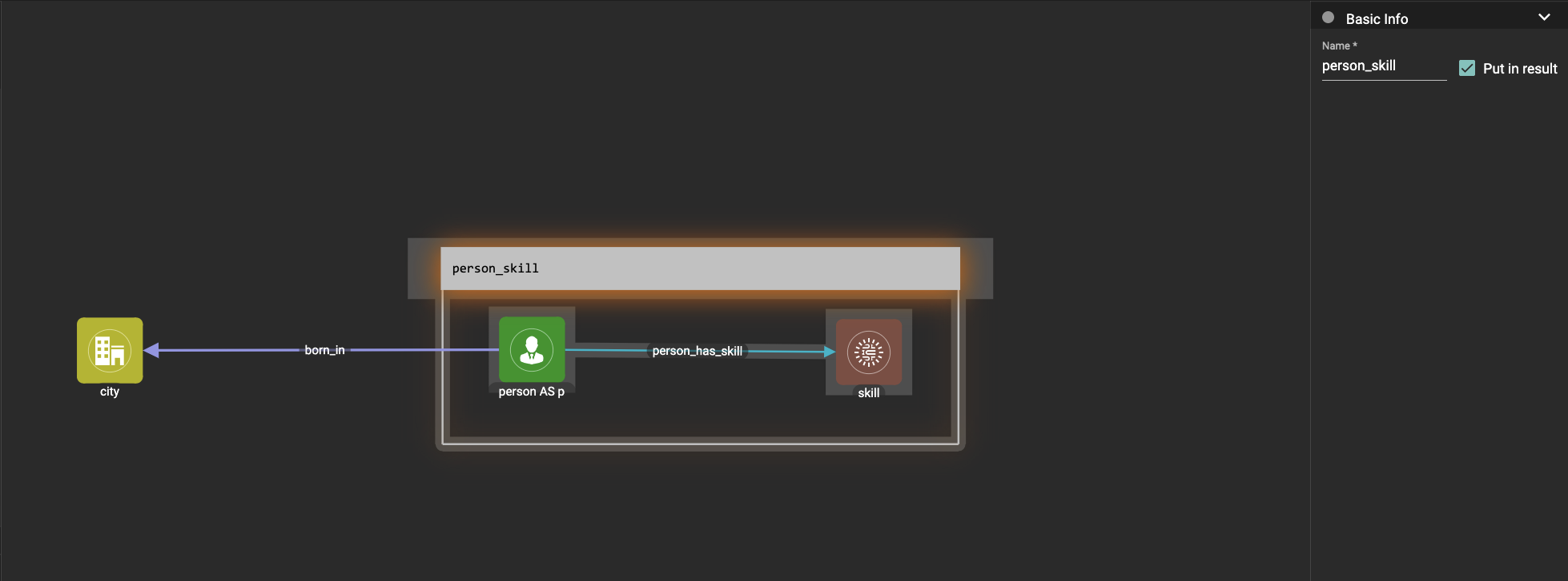
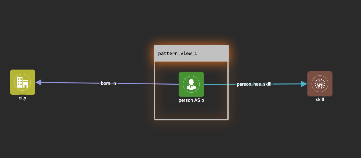
Here we have a pattern view that includes part of a visual pattern:
Running this visual pattern would give us the following result:
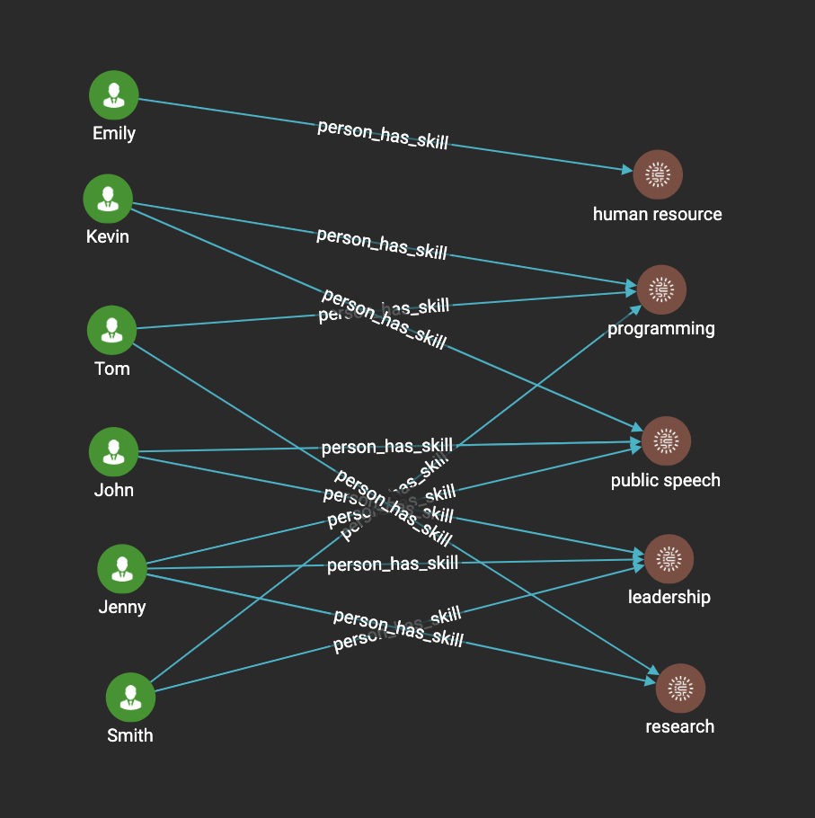
As you can see putting a pattern view over a part of the visual pattern would mean applying the pattern view on only a sub-graph of the pattern match result of the whole pattern.
In this case, it is the sub-graph which matches the sub-pattern (person AS p)-person_has_skill→(skill). In this case the output of the pattern view is just the sub
-graph of the pattern match result.
Example 2
Here we have a pattern view that includes the whole visual pattern:
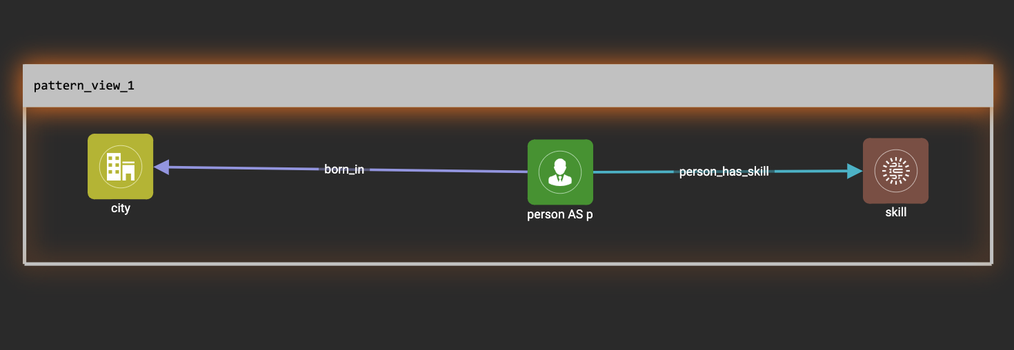
Running this visual pattern would give us the following result:
As you can see putting a pattern view over the whole visual pattern would mean applying the pattern view on the pattern match result of the whole pattern. In this case, the output of the pattern view is just the projection of the whole pattern match result again.
Example 3
Here we have a pattern view which includes only a vertex within the visual pattern:
Running the visual pattern would give us the following result:
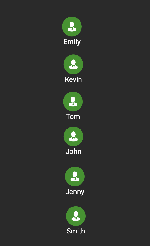
As you can see putting a pattern view over only a vertex within a visual pattern would mean applying the pattern view on only a single vertex type of the pattern match
result of the whole pattern.
In this case, it is all the vertices of type 'person'.
The output of this pattern view is just the projection of all the distinct vertices of
type person within the whole pattern match result.
This is the same behavior as when we just output a single vertex.
Limitations
-
Overlapping pattern views are not allowed:
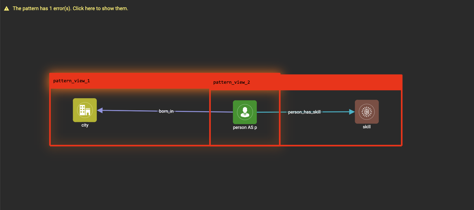
-
Pattern views across different connected components are not allowed:
-
Vertex patterns within a pattern view cannot be merged with any other vertex patterns:
-
We currently do not allow creating edge patterns between vertex patterns in the same pattern view:
-
Drag-and-drop is not supported within a pattern view. However, the pattern view itself can be dragged around, and the vertex and edge patterns within it will be dragged along with the pattern view.
Widget
As described in the Basic Concepts, a visual pattern represents a graph pattern matching problem. In graph theory, graph pattern matching is declarative. However, graph pattern matching is not the full story. In a lot of cases you need to represent procedural computation flow. That’s why we are introducing widgets.
Intersect
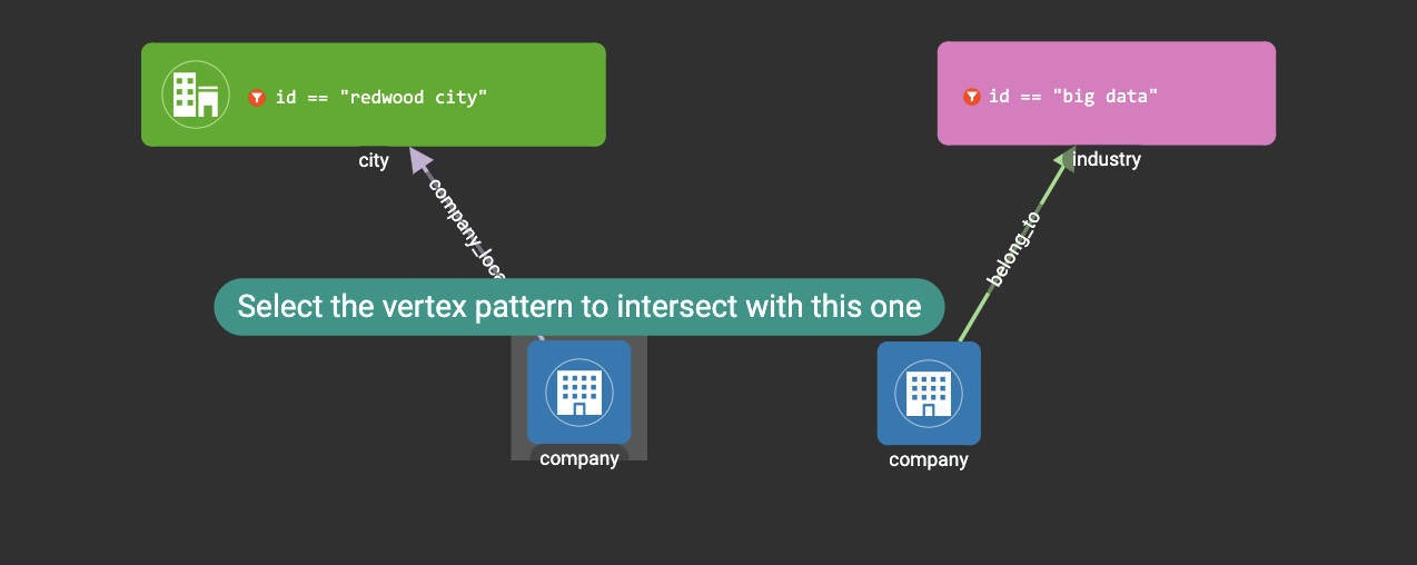
Click  , then click two
vertex patterns of the same vertex type:
, then click two
vertex patterns of the same vertex type:
And an intersection widget is added to the visual pattern:
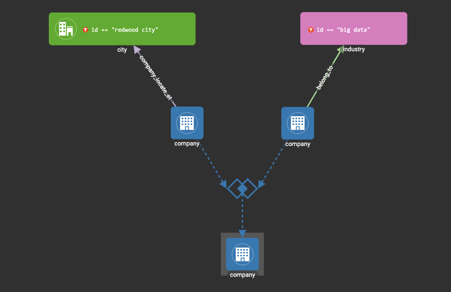
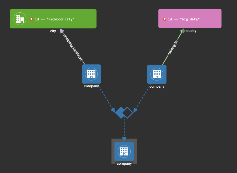
The output vertex pattern means matching all company vertices located at redwood city, and belongs to big data industry.
The output company vertex pattern can be part of another larger pattern. You can think of the input vertex patterns of the widget as constraints of the output vertex pattern.
Union
Click  , then click two
vertex patterns of the same vertex type. A union widget is added to the visual pattern:
, then click two
vertex patterns of the same vertex type. A union widget is added to the visual pattern:
The output vertex pattern means matching all company vertices located at redwood city, or belongs to big data industry.
Subtract
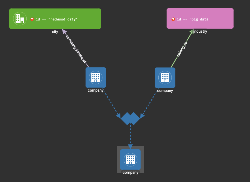
Click  , then click two
vertex patterns of the same vertex type. A subtract widget is added to
the visual pattern:
, then click two
vertex patterns of the same vertex type. A subtract widget is added to
the visual pattern:
The output vertex pattern means matching all company vertices located at redwood city, but not belong to big data industry.
Within
The Within widget allows you to create a vertex pattern whose matching result is constrained within the matching result of another vertex pattern.
For example, say you have a vertex pattern for all people who currently work at company A, and you want to select from them everyone who has bought product B. You can use the Within widget to select from the vertex pattern with all person vertices that work at company A, and create another pattern for people who have bought product B. The output from the second pattern will be a subset of the matching result of the first pattern - that is, the output from the second pattern will be people who work at company A, who bought product B.
Click  , and then select a vertex pattern whose result you want to select from.
This creates a within widget on the first vertex pattern, and you will see a second vertex pattern added to the graph pattern.
Below are two visual examples to select results within a vertex pattern.
, and then select a vertex pattern whose result you want to select from.
This creates a within widget on the first vertex pattern, and you will see a second vertex pattern added to the graph pattern.
Below are two visual examples to select results within a vertex pattern.
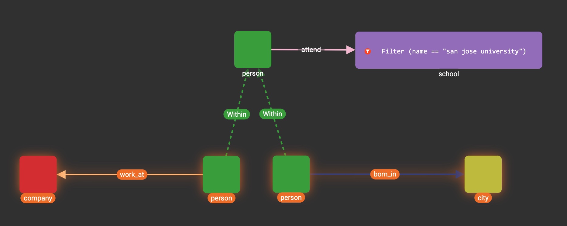
In the above example, the graph pattern outputs two bottom patterns which are both within the top pattern.
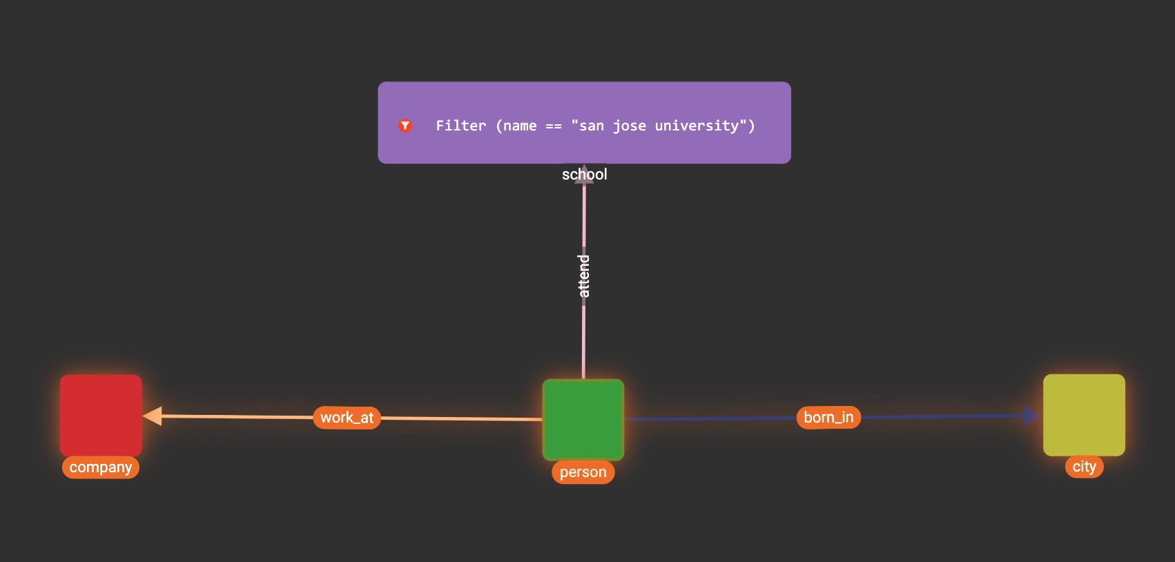
The output vertex pattern means matching all company vertices or all city vertices that a person who attends san jose university is working at or was born in.
In other words, a person vertex that attends san jose university needs either a work_at edge connected to a company vertex, or a born_in edge connected to a city vertex to be included in the result.
The output vertex pattern means matching all company vertices and the city vertices that a person who attends san jose university is working at and was born in. In other words, a person vertex needs to have both a word_at edge connected to a company and a born_in edge connected to a city to be included in the result.
Downward import
We now support importing visual patterns from a higher version to a lower version.
Here is an example of the dialog that will be shown when an imported solution contains visual patterns which contain features that are unsupported in the current version:
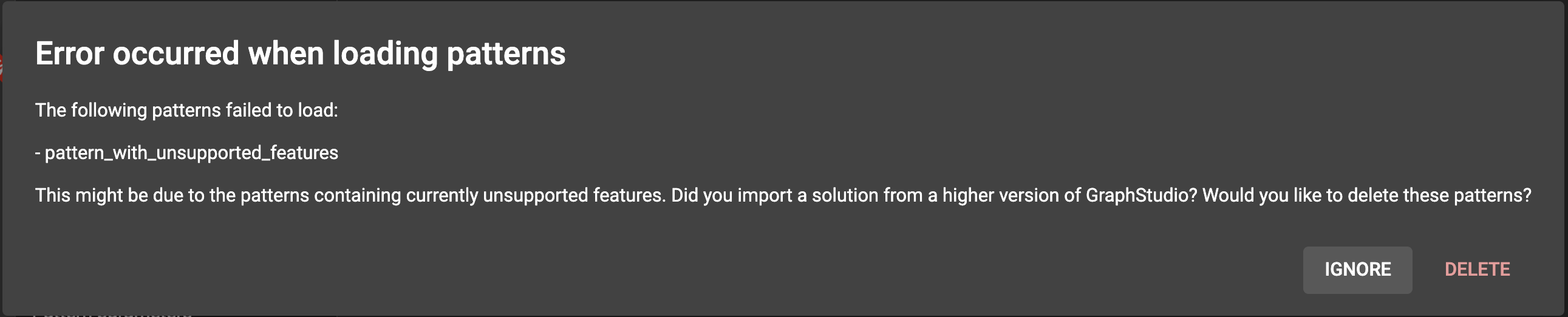
Users can choose to either ignore the message and keep the pattern or delete it. If the user chooses to ignore the message and keep the pattern, the pattern will not be deleted, but it will not be displayed or accessible to the users.